The rationality of using safety circuits with 2oo3 voting system
RBI Concept Company - a service provider for HAZOP (Hazard and Operability) analysis, has been conducting risk sessions for quite some time and during this period has analyzed numerous project documents based on which HAZOP risk sessions were conducted.
Article Purpose
To justify the exclusion of designing SIS safety loops when applying 2oo3 voting system to reduce design and operational costs.
Problem Description
Even at the preliminary document analysis stage, we identified similar design approaches that unjustifiably increased the Customer's expenses for design, construction and installation work, and subsequently, operational costs.
As a rule, we inform the Customer about such issues, but the decision remains with them. We want to draw your attention to one of the most frequently encountered aspects.
In practically 90% of project documents, SIS safety loops have a 2oo3 voting system. What does this mean? This means that one critical parameter, for example pressure, is simultaneously monitored by 3 transmitters using a 2 out of 3 voting system. If 2 out of 3 transmitters trigger, the Safety Instrumented System (SIS) is activated.
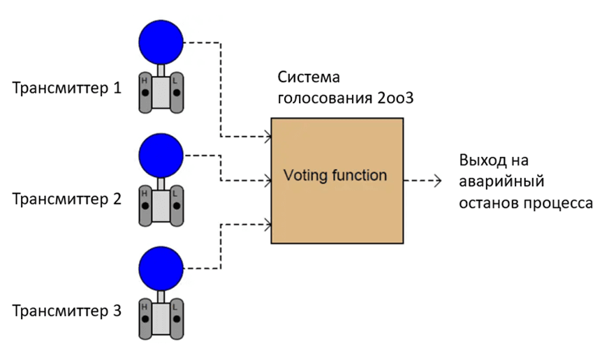
During risk sessions, HAZOP working group engineers from the Customer side are focused on reducing the SIL level of SIS safety loops to SILa level using existing protection layers, which allows using these loops in DCS, but the sensors remain in the project with a 2 out of 3 voting (redundancy) system.
Let's try to understand in which cases such a voting system is necessary and when it is assigned.
Rostechnadzor Requirements
Let's consider one of the important regulatory documents of Rostechnadzor concerning chemical, oil and gas production, petrochemical and oil refining enterprises, though the regulator's approach is similar in other industries of the Russian Federation. This is Order No. 533 of December 15, 2020 "On approval of federal norms and rules in the field of industrial safety 'General explosion safety rules for explosion and fire hazardous chemical, petrochemical and oil refining production facilities'".
In these rules, an entire chapter (paragraphs 218-292) is devoted to requirements for designing SIS systems at hazardous production facilities.
In particular, paragraph 236 of the Rules states: "Monitoring of current parameter indicators determining explosion hazard of technological processes with Category I explosion hazard units is carried out by at least two independent sensors with separate sampling points, logically interacting for SIS activation". That is, there are requirements for using at least 2 sensors in Category I explosion hazard technological units.
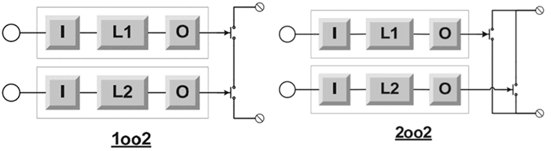
The sensor connection scheme is not standardized, meaning any scheme shown in Fig.2 can be used.
Additionally, RTN Order No. 533 establishes SIS reliability indicators for at least two types of system failures: "fail to operate" failures and "spurious operation" failures.
When a dangerous event occurs in the process and the SIS cannot respond to it, such failure is called a "dangerous failure".
When the SIS performs a false unmotivated emergency process shutdown, this is called a "spurious or safe failure".
Conclusion for this chapter: there are no regulatory requirements for using sensors with 2 out of 3 voting system in Order No. 533 requirements.
How is the 2oo3 Voting System Selected?
To understand how the selection of 2 out of 3 voting system in SIS safety loops is standardized, it's necessary to refer to the GOST R IEC 61508 and 61511 standards series on which SIS design is based.
The first thing to note in these standards is the functional safety system lifecycle, where SIS is part of it.
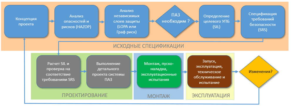
From the diagram in Fig.3, we see that the first step in SIS design is risk assessment (probability of hazard realization and its consequences), which are determined through HAZOP analysis.
After determining risks using HAZOP method, we need to assess existing facility protection measures using LOPA independent layers methodologies or Risk Graph described in GOST R IEC 61511-3-2018. This is visually shown in Fig. 4.
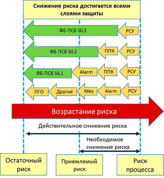
Using LOPA or Risk Graph methodologies, we determine the target SIL level that reduces risk to an acceptable level. In this case, there is also no discussion of any voting system in sensor connections.
When protection layers are sufficient and risk is closed, there is no need to use SIS safety loops (or safety functions of instrumented safety systems according to GOST R IEC 61508), see bottom row in Fig.4. But this is only if there's no contradiction with SIS design requirements in RTN Order No. 533, which has unconditional priority over GOSTs.
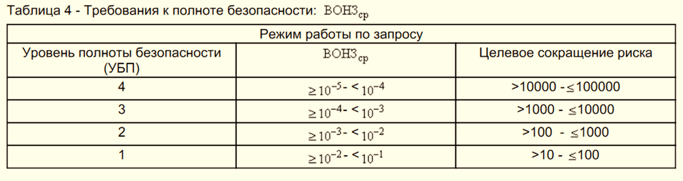
After assigning the target SIL level according to the table in Fig.5, we can confidently proceed to SIS design, i.e., prepare safety requirements specification by which SIS safety loop elements are selected: sensor, controller, actuator. See Fig.3.
Our goal in SIS design is achieving the target SIL level determined at the LOPA or Risk Graph analysis stage.
SIS safety loop elements are supplied with characteristics indicating 4 types of failure probabilities: safe detected, safe undetected, dangerous detected, dangerous undetected.
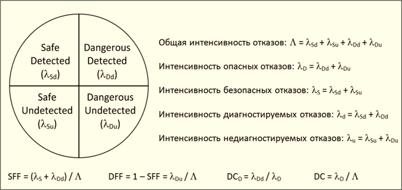
One of the key parameters determining the Safety Integrity Level (SIL) is the Safe Failure Fraction (SFF), directly related to failure rate and determined by the formula:
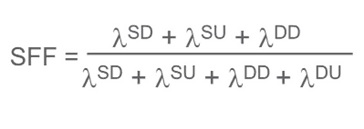
The higher the SFF, the higher the built-in diagnostics, which allows assigning a higher SIL level. From the equation, it's clear that the fewer undetectable dangerous failures (λdu), the higher the SFF.
The next step in verifying target SIL level achievement is determining the voting system or need for hardware redundancy, which is conducted according to GOST R IEC 61508-2 tables shown in Fig. 7.
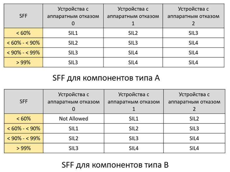
Hardware redundancy determination, where:
- Group A: simple devices whose failures are easily diagnosed (valve, relay, switch, solenoid, etc.)
- Group B: complex computerized devices whose failures are unknown or difficult to diagnose (smart transmitters, controllers, positioners, etc.)
Hardware Fault Tolerance level from 0 to 2 shows how many failures can occur before device failure. Essentially, these are redundant channels.
For example: HFT=0 is a 1oo1 voting system, HFT=1 is a 1oo2 or 2oo3 voting system, HFT=2 is a 2oo4 voting system.
Conclusions on SIS Safety Loop Voting System
SIS safety loop voting architecture is determined only at the SIS design stage, after HAZOP and LOPA/Risk Graph, and only to achieve the target SIL level.
There is no need to universally use 2oo3 system in SIS loops, as this only increases project cost and operational expenses.
In the SIS safety loop design process, the obtained Safety Integrity Level (SIL) must not be lower than the target SIL determined by LOPA or Risk Graph method, so that existing risks are addressed.